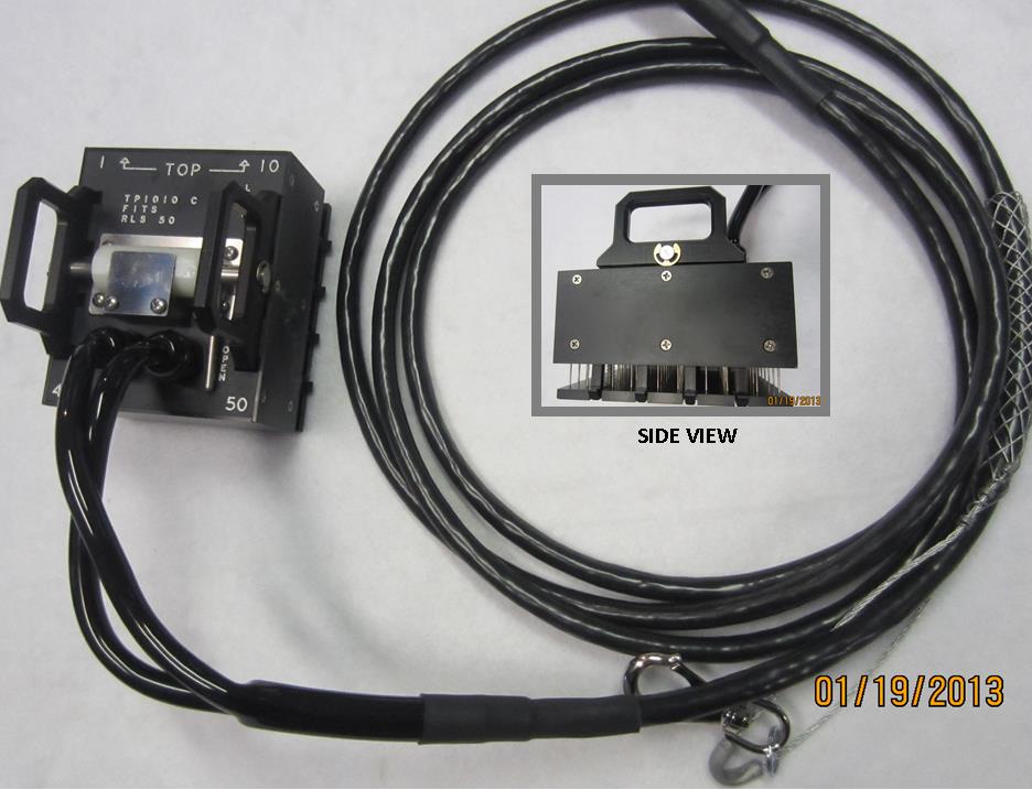
TP1010
TP 1010
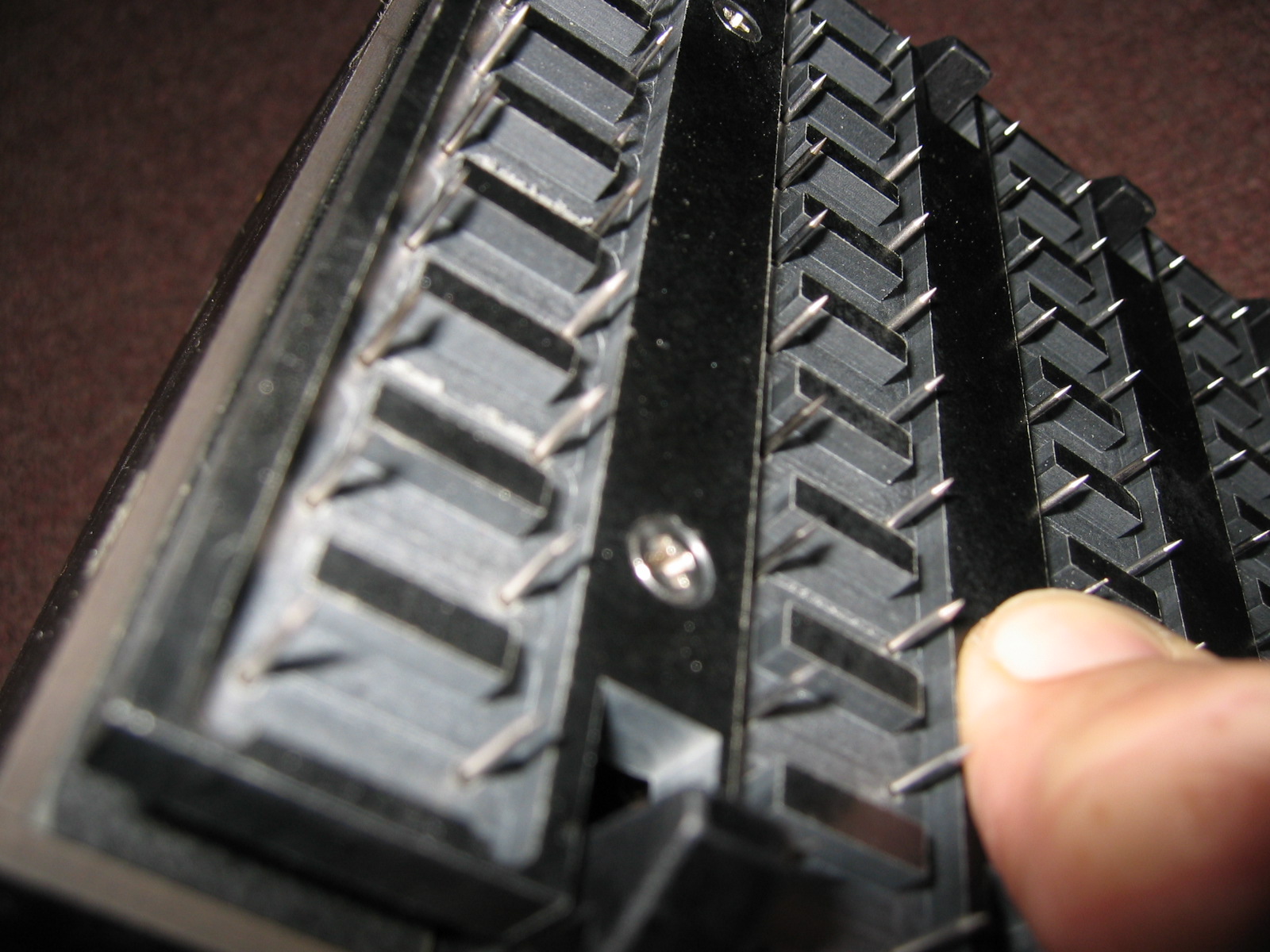
TP1010 pins
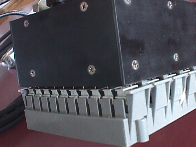
TP1010 Connected to RLS-50
RLS 50
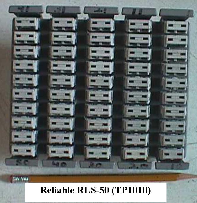
The TP 1010 Front Tap Shoe is designed for use with the Reliable RLS-50 cross connect terminal.
*Please note: due to the obsolescence of Cinch Jones connectors, all our Front Tap Shoes are now manufactured with male bail lock AMP connectors.
See details/descriptions at http://www.customassemblyinc.com/testequipment/
Repairing or Replacing pins on the TP1010
Remove the two screws (8-32 x 1 ½ “ panheads) connecting the stay plate and stay block to the top .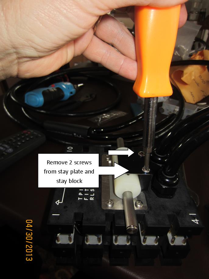
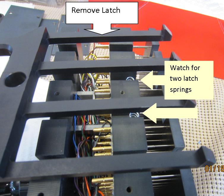
Pull E-style 3/8 Retaining Rings from Latch post using a pliers and remove latching mechanism.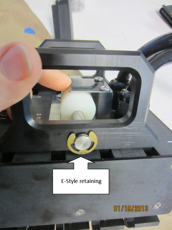
Remove 4 screws (8-32 x 7/8 panheads) from top metal plates – Note: these are screwed into hex standoffs within the interior of the part: 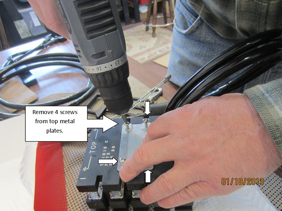
Remove all flathead screws (6-32 x 3/8”) from all side plates: 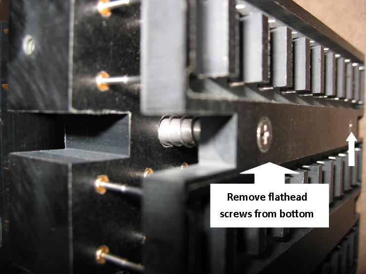
Pull out rake-like latches, being mindful of the latch springs (4 total-2 per side):
Remove four flathead screws (4-40 x 7/16”) from base plate (using 2 screwdrivers works best). Be mindful of the springs on the stand offs which the screws are attached to: 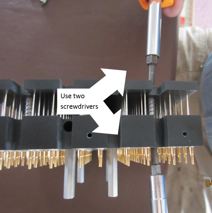 Remove base plate and guide plate (may want to take off springs and set aside) then you will have access to remove/replace pins.
REMOVING or REPLACING PINS:
If pin is broken and still above the plate, grab with a pliers and pull out.
If pin is broken off flush with the plate, use a small drill bit #43 (.089) put slight amount of lateral pressure on the drill bit and pull out the broken pin. You can also use a very small e-z out.
Replace new pins (CAI Part # 93-B-024-R1, sharp spearhead pins) by lining up in hole and pushing down until it snaps into place.
See pin repair/replacement video at http://www.customassemblyinc.com/news/repair-service/5
WHEN FINISHED FIXING PINS: Replace all pieces of Front Tap Shoe in reverse order. NOTE: Make sure all wires are clear of standoffs before you tighten screws. If wires are caught, they could be cut.
The TP 1010 consists of the following components:
- Field replaceable probes.
- Machined plastic pin housings.
- A 15 foot, 50 pair 28 AWG gauge stranded (7/38) tinned wire cable; soldered terminations.
- Customized latch mechanisms to assure proper connection and contact (see Installation Tab).
- Two 25 pair Female Cinch Jones connectors or Amps depending on customer's needs.
- While holding handles outward (so that latches pull in), align probes with block slots.
- Pull down locking lever so that the latches pull the Front Tap Shoe down and the probes lock into place.
- IMPORTANT: When removing Front Tap Shoe, pull up the locking lever, then pull out the handles to release the latches.