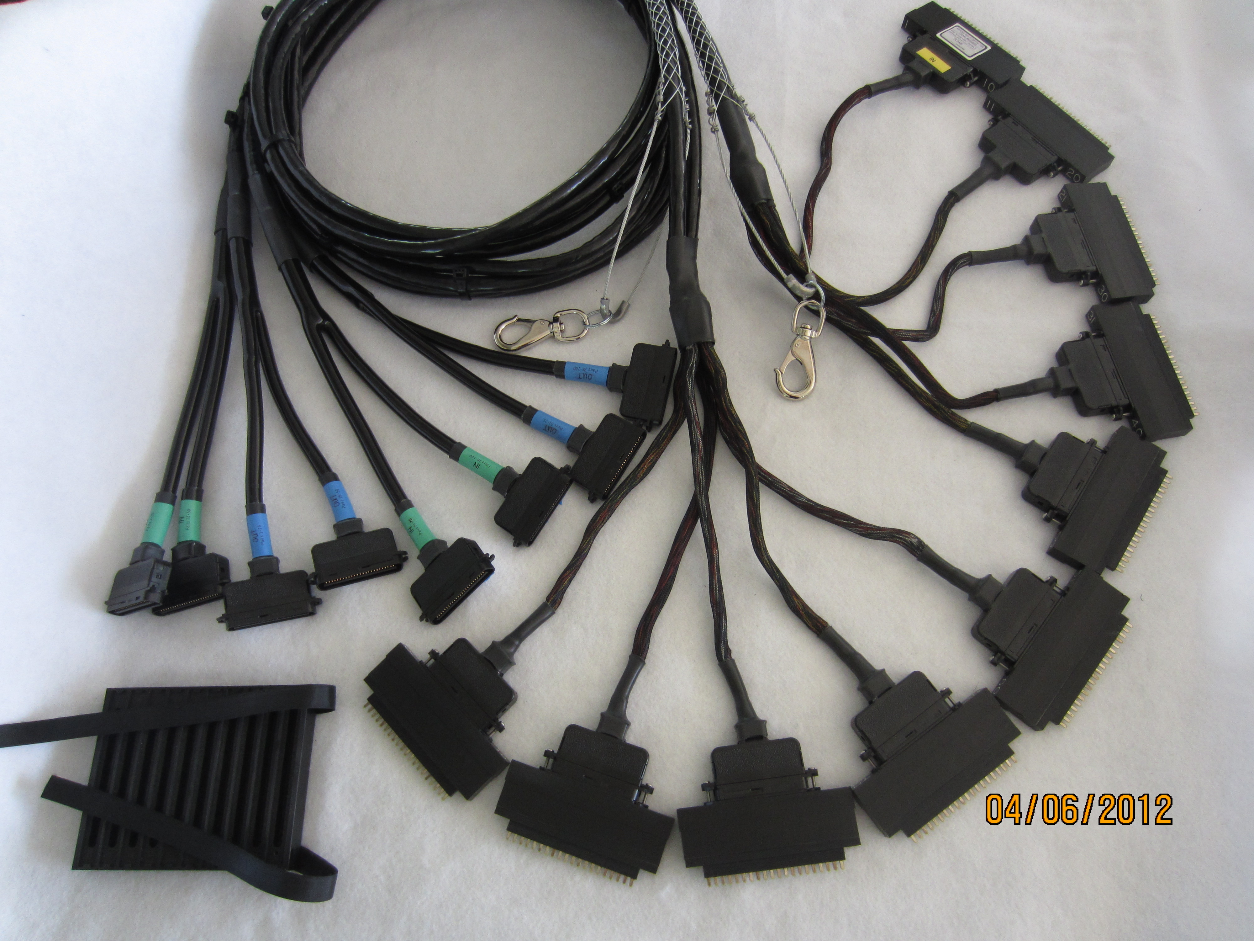
TP1087-100 PRAM
TP1087-100 PRAM
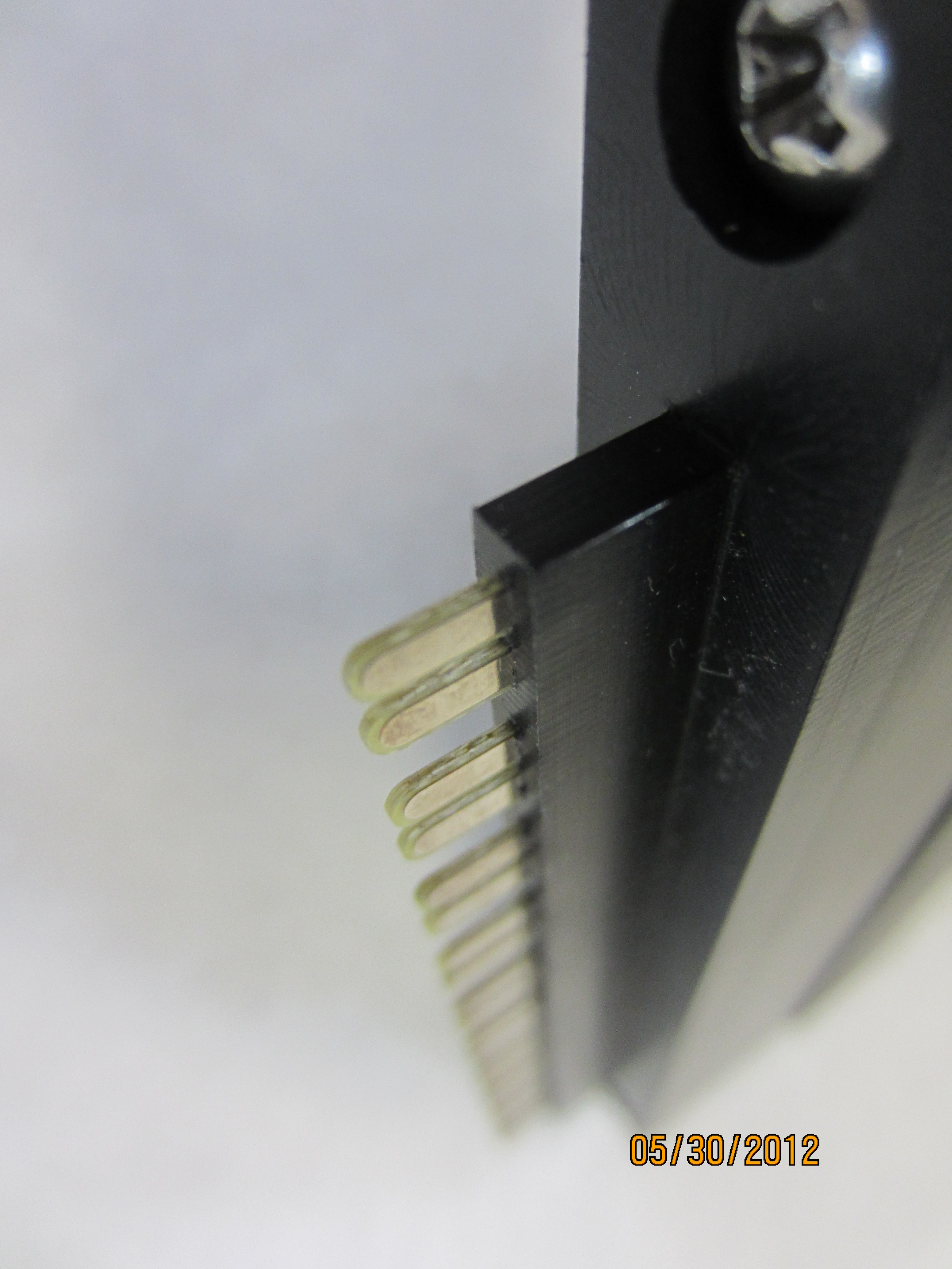
TP1087-100 PRAM double pins (two-sided)
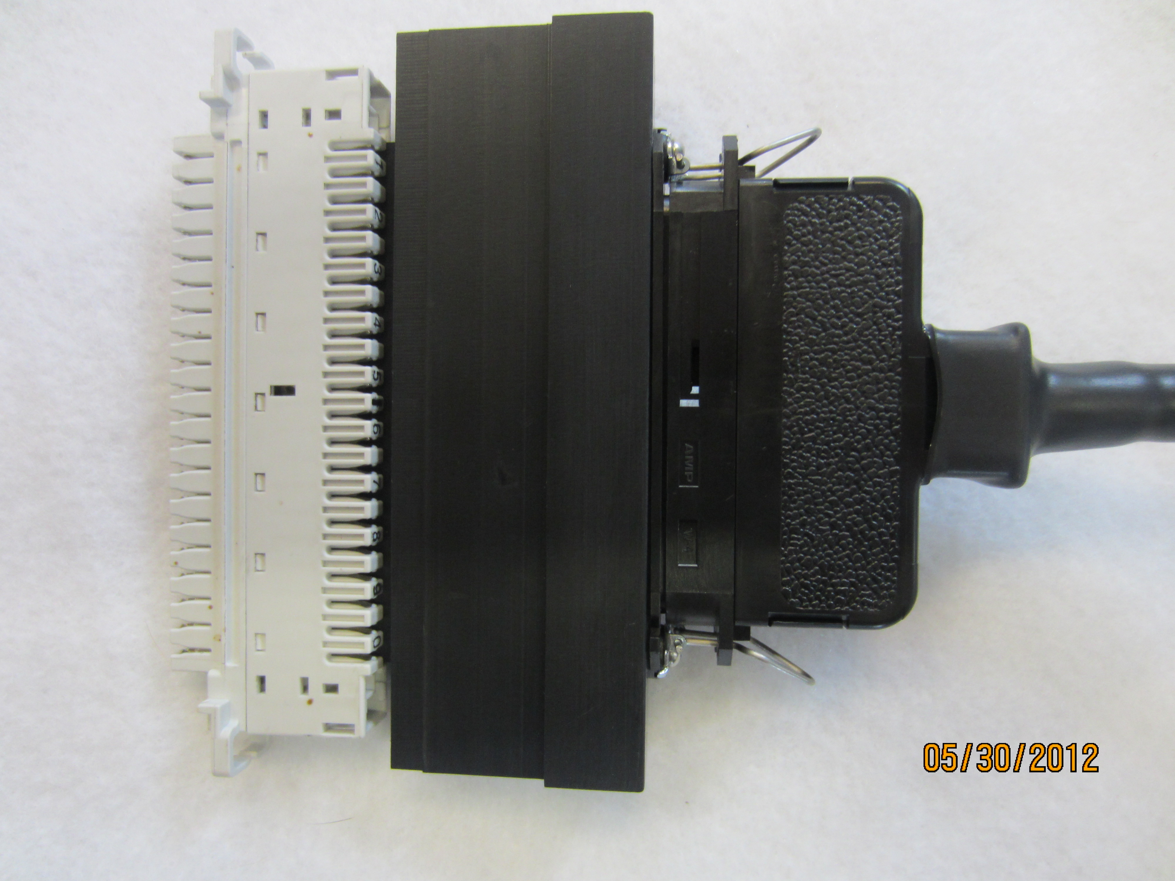
TP1087-100 PRAM on block (Krone LSA+ HD)
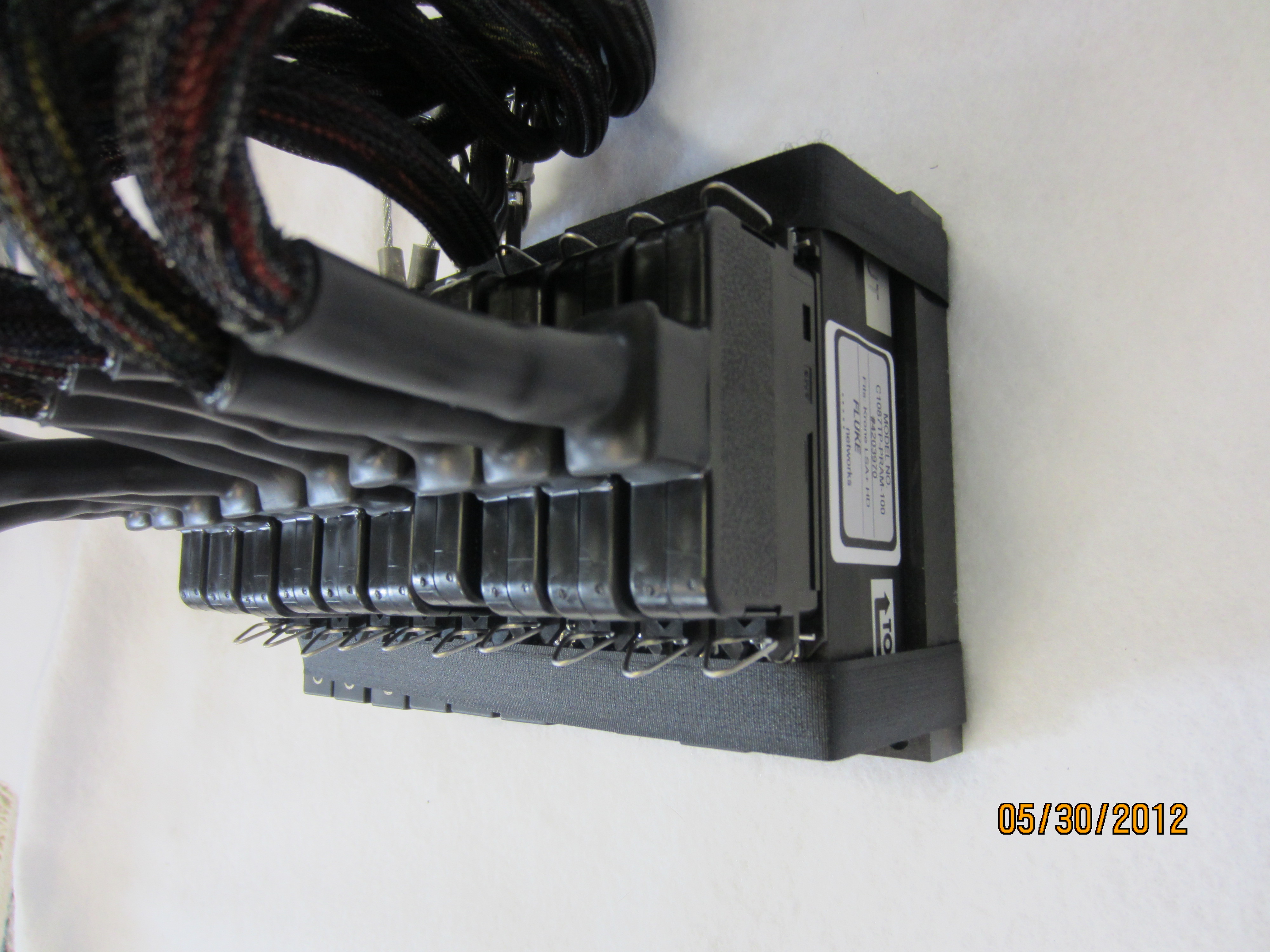
TP1087-100 PRAM in protective case
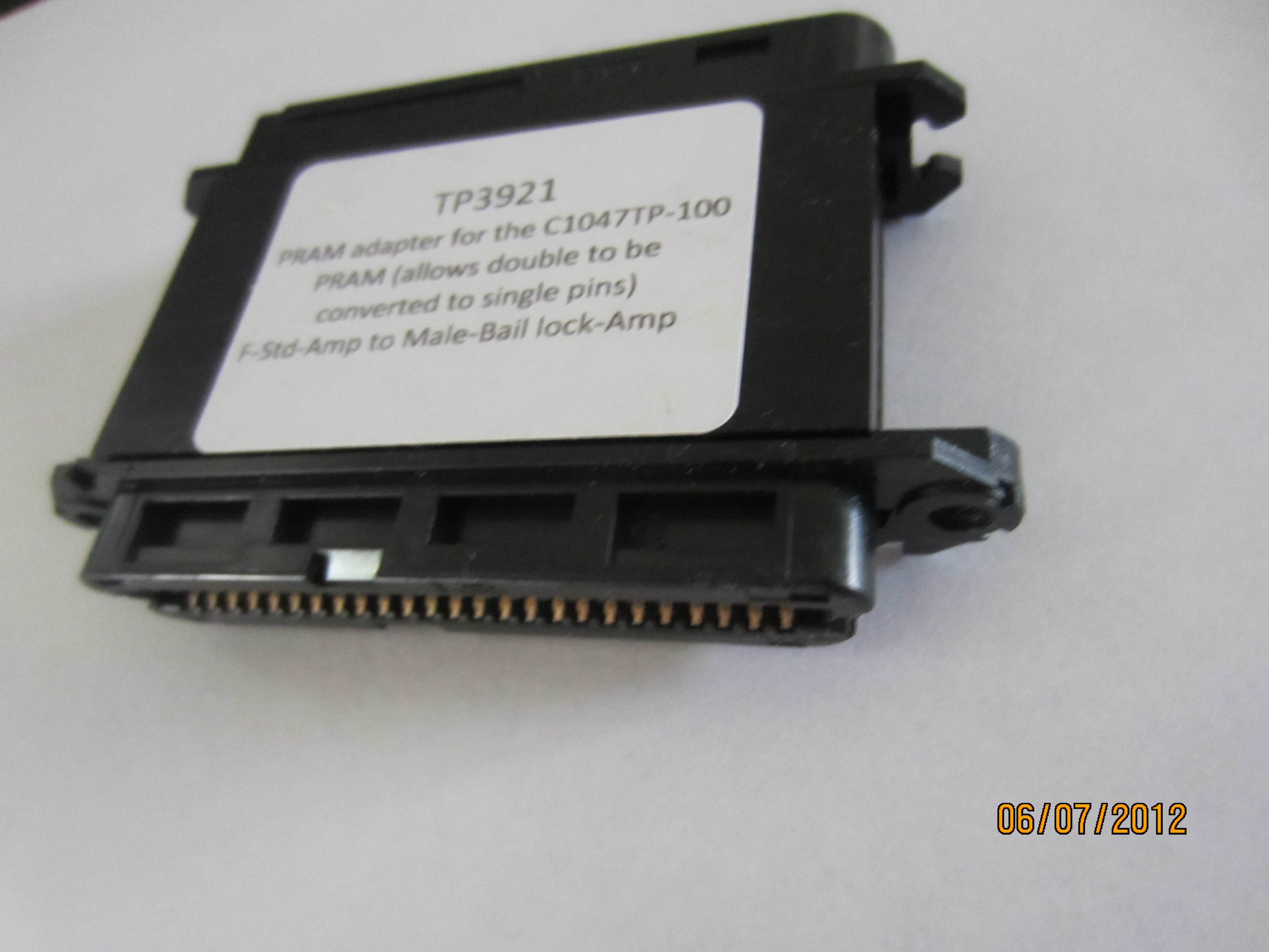
TP3921 adapter (converts double pins to single pins)
The TP 1087-100 PRAM is a double pinned Front Tap Shoe designed to fit the Krone LSA+ HD. Krone LSA + series 2 PRAM will not work on Connection Modules( see below for details). The FTS is built to work with PRAM and consists of the following component:
- Ten individual heads; Ten pair of double pins each (IN/OUT)
- Four 15 foot, 50 pair 28 gauge stranded (7/38) tinned wire cable; soldered terminations.
- Eight male bail lock AMP connectors.
*Please note: due to the obsolescence of Cinch Jones connectors, all our Front Tap Shoes are now manufactured with male bail lock AMP connectors.
See details/descriptions at http://www.customassemblyinc.com/testequipment/
NOTE: The TP1087-100 PRAM is compatible with the TP3921 adapter
For further explanation, please visit these links:
|
Krone LSA + series 2 PRAM will not work on Connection Modules. |
|||
|
Look at pg 4 on this one |
|
||
|
http://www.adckrone.com/in/en/library/brochures/Carrier/connectivity/LSA-PLUS_400255IN.pdf |
|||
|
|
|||
|
|
|||
|
Look at pg 14 on this onehttp://www.adckrone.com/eu/en/webcontent/support/PDFs/carrier/103629BE.pdf |
|||
|
Connection module |
|
|||
|
The functional principle of the LSA-PLUS connection module is |
|
|||
|
based on an unbreakable connection. On the system/cable side and |
|
|||
|
the jumper side, the cable leads are connected to the contacts |
|
|||
|
arranged opposite one another. In the centre are separate contacts |
|
|||
|
for each pair, which, for example, can be used for measurement |
|
|||
|
and testing work, for switching using switching adapters or for |
|
|||
|
inserting overvoltage protection magazines (3-point protection with |
|
|||
|
overvoltage protection contact arrestors or semiconductor elements). |
|
|||
|
The casing is grey. |
|
|||
|
|
||||
|
Disconnection module |
|
|||
|
With the LSA-PLUS disconnection module, the connection can be |
|
|||
|
broken by placing a disconnection plug in the normally closed |
|
|||
|
contact between the connection contacts. Using patch and test cords, |
|
|||
|
it is possible to create a wide variety of different circuits for measuring and |
|
|||
|
testing. The disconnection module principle is particularly suitable for realising high-quality protection |
||||
|
concepts. The casing is white. |
|
|||
|
|
||||
|
Switching module |
|
|||
|
With the LSA-PLUS switching module, the individual connection contacts and up to 40 idle circuits are |
||||
|
disconnected. By adding plugs or cords, circuits can be connected if necessary or used for measuring and |
||||
|
testing purposes. The installation of 5-point or graded protection is also possible. The casing is brown or, |
||||
|
in the LSA-PLUS NT modules, yellow. |
|
|||
|
|
||||
|
Earth module |
|
|||
|
Depending on the design, the LSA-PLUS earth modules enable up to 84 cable leads to be laid to a common |
||||
|
electrical potential. Via a securely connected flexible earth line, the earth potential to a backmount frame or |
||||
|
to an earth terminal is established. The casing is red. |
||||